|
|
|
|

IntroductionThis page will focus on the building of the first studio scale replica of the original (as in first) model of the Enterprise. That model was built first, was the first model to go before the cameras (in "The Cage") in December 1964, and the last to go before the cameras (in "Requiem for Methuselah") in December 1968. 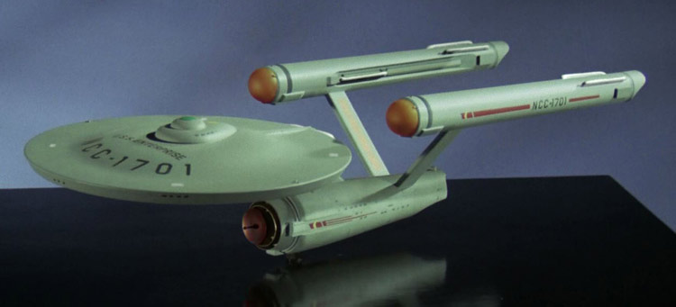 This project as a whole began back in 2007. By that time a number of commercial groups (Unobtainium Ltd. and Master Replicas) had attempted to usurped the term "studio scale" for their products that were 1/350 scale replicas of the Enterprise based on the 11 foot studio model. The problem is that the original 33 inch studio model was both physically different from the 11 foot model (apart from their overall sizes) and the approximate scale was 1/333, not 1/350. The original 33 inch model was actually 33.75 inches long, compared to the 1/350 scale models which are about 32.4 inches in length. The waters have been further muddied since then by companies putting out approximately 3 foot models of Star Trek subjects that were CGI on screen, but then called them "studio scale" (the 2009 movie version and the 2018 television version of the Enterprise are perfect examples). A studio scale replica should, at the very least, be based on a physical studio model. A better term for representations of a CGI subject that is based on the original files would be "authentic". When I first approached the idea of documenting/making the 33 inch Enterprise there was very little to work with for references. People had been trying to make accurate representations based on the 11 foot model since the late 1960s, and even with that model on display in the Smithsonian since the mid 1970s, the first reasonably accurate replica didn't show up until the mid 1990s (Greg Jein's half studio scale model for the Deep Space Nine episode "Trials and Tribbleations"). The first accurate kit (based largely on the same information used by Jein) was the 1/1000 scale model from the early 2000s. Given the access to the existing 11 foot model and the time it took before a somewhat reasonable approximation showed up (literally decades), a lot of people considered a replica of the 33 inch model most likely out of reach. To me it sounded like an interesting challenge. I started by taking newly released data on measurements from Matt Jefferies' original plans for the models and reverse engineering them using a couple small samples of the original. With that I started work on reverse engineering the unique contours of the 33 inch studio model from existing references and pulling them together into a set of plans. I knew that the plans were flawed, but also knew that the best way to find them was to construct a model (physical or CG) based on them and do comparisons against existing photos of the original. Having not built a model since the early 1990s, I figured the best course was to make the plans available to everyone and let someone with a reasonable skill level take a shot. By 2008, with no one seeming to make any attempts, I decided to attempt a study model myself. Knowing that the AMT/ERTL 22 inch Cutaway Enterprise model was based on Allen Everheart's plans of the Enterprise (which I had a copy of), I determined that I could convert some elements and scratch build others to make a two-thirds scale representation. I completed my first attempt in 2009, applying what I learned from that build back into my plans. With improved plans and an improved model building skill set, I started a second two-thirds scale study model which I finished in 2010. Once again I applied what I learned from that model back into my plans and started feel pretty confident in their overall accuracy. I spent a lot of 2010-2012 watching Steve Neill build his half studio scale representation of the 11 foot Enterprise model, attempting to pick up as many techniques as I could. Right as I was about to start this build in 2012 I was given a lot of additional information about the Phase II Enterprise (another project that I started back in 2007). I saw this as both an opportunity to act on this new information and to test out some of the techniques I had gathered from watching Neill's build. I set this build aside and spent 2012-2014 building a study model of the Phase II Enterprise. The completion of that model brings us to the start of this one. Why call this The K2 Project? Replicating the Enterprise has been the goal of many fans of the original series since it started airing back in the 1960s. While the design seems simple, it turns out to be very hard to copy (this is a hallmark of most elements of the original series). As pointed out, it took almost 30 years to scale that mountain. But shortly after Jein had produced his model, others would follow, to the point where making accurate models based on the 11 foot studio model are (while still difficult) rather common. This reminded me of a photo of a seemingly endless line of climbers ascending Mount Everest. The climb may not be a trivial undertaking, but it isn't the rare feat it once was. By comparison, very few people have scaled K2 (the second tallest mountain), with many of those attempting it either failing or dying in the process. To me, the 33 inch Enterprise seemed like the K2 compared to the Mount Everest of the 11 foot model. And when I started, many people didn't even think it was possible to do. So that was the inspiration for the project name. Where To StartBy this point I had built two study models (at about 1/500th scale), the Phase II Enterprise (also at 1/500th scale) and started a study model of the 11 foot studio model (at one-sixth studio scale, or about 1/500th scale). All these models had two things in common... they were all about the same size and I had always modified an existing secondary hull from another model kit. I assumed that (for the most part) the techniques I used for scratch building all the other elements would work even when scaled up, so I picked the secondary hull as a starting point for this model. Looking at my plans, I opted to build a universal secondary hull master. Something that could produce both sides of the structure. I omitted all other details other than the slots for the nacelle supports and started in on building. I began with a foamcore board structure, filled that with foam blocks, cut those to shape with a hot wire, and then used a scree template of the hulls contours to build up a plaster surface. 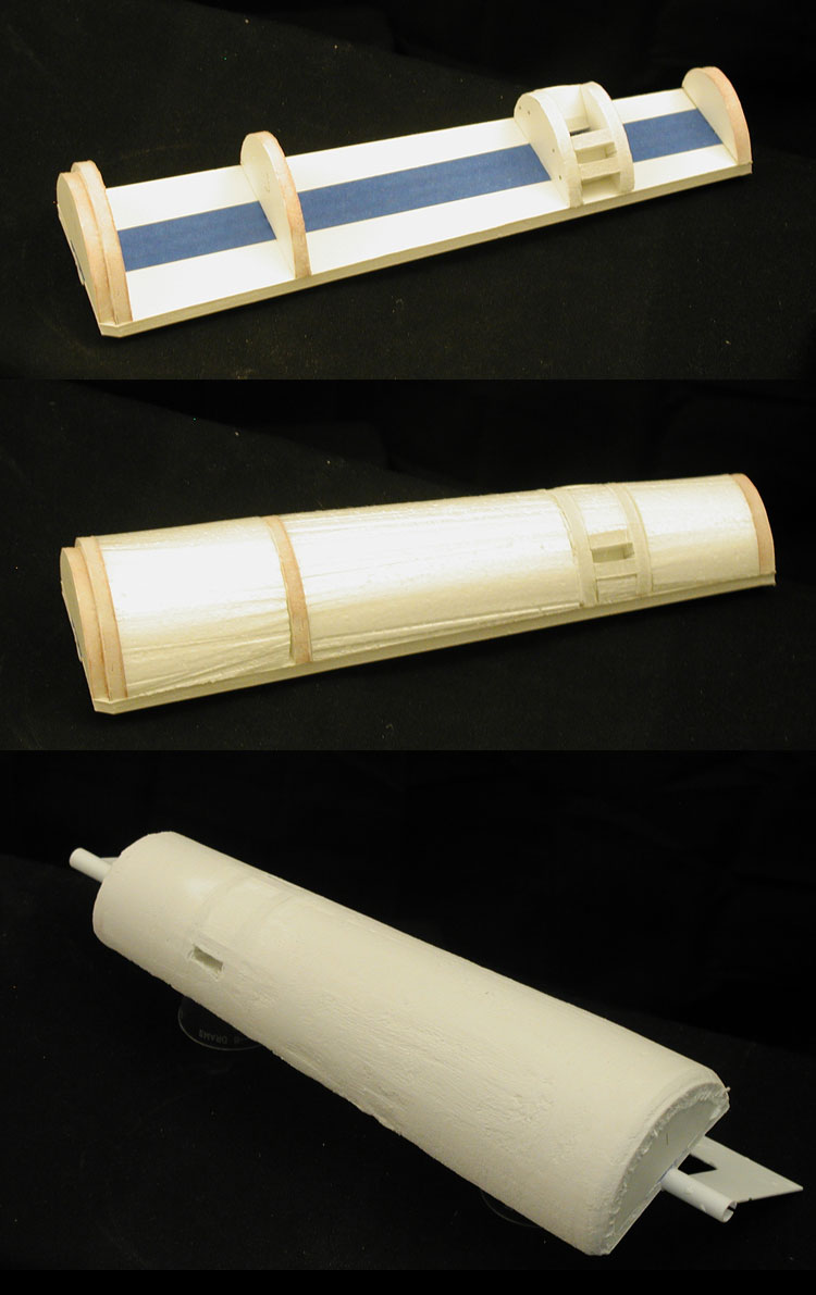 For the nacelles I took a different approach. I started with large cardboard tubes designed for model rockets that were close in diameter to the nacelles. I made paper templates for one half of the nacelle body and used them to cut the pieces I needed from the cardboard tubes. I also made a template of the opening on the inner side of the nacelles for cutting that out. Both sides were mounted on pieces of foamcore that matched the contours of the nacelle body, and when brought together formed a nice representation of a nacelle. 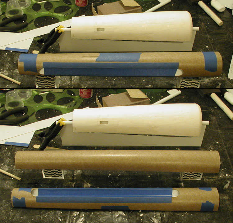 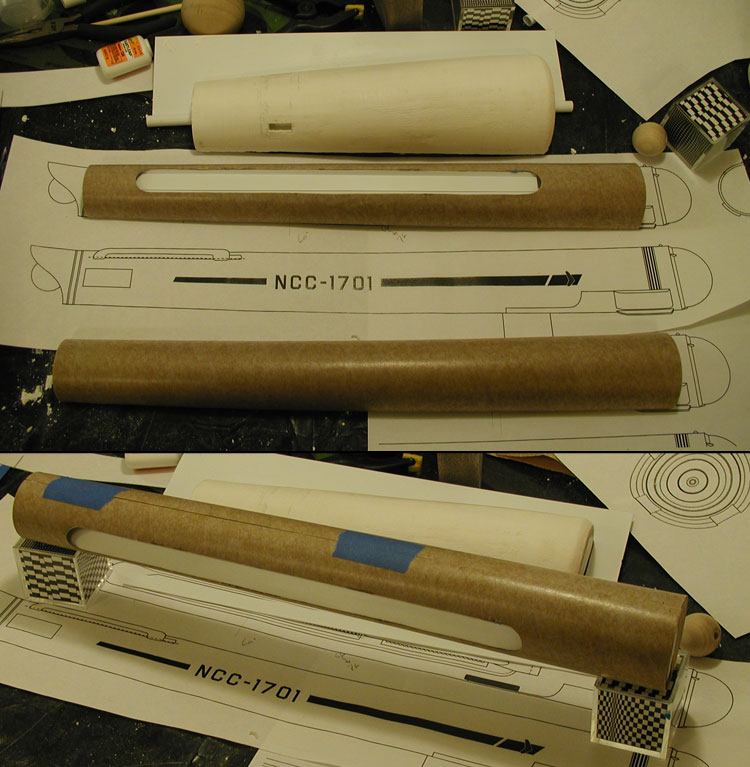 Like with the secondary hull master, these were universal parts for making both nacelles. So I also built in the openings for both nacelle support attachment points on the inboard nacelle master. The cavities in both the secondary hull and nacelle masters were designed to make sure that the final parts would align correctly. 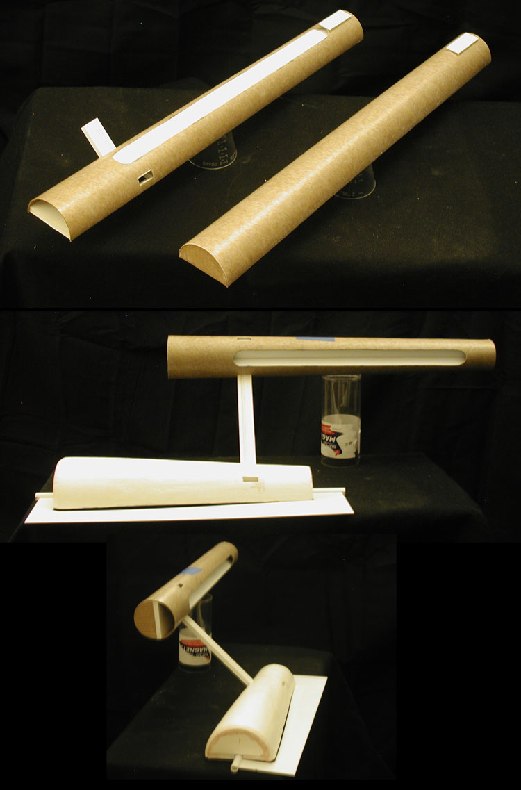 The Next Major StepOnce I felt that I had the alignment of the secondary hull and nacelle masters, the next step was to start in on the primary hull. I cut the contours of the upper and lower primary hull out of styrene and then built up a rough mock up of the shapes on a couple of boards. I used some styrene tubes to make my contour templates rigid enough for turning the patterns. 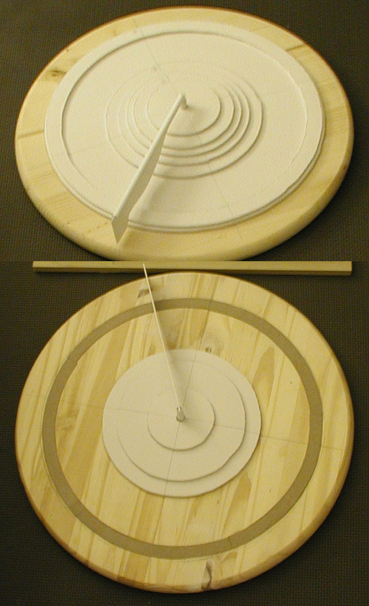 I next mixed up some plaster and over a series of applications started to build up the shapes. 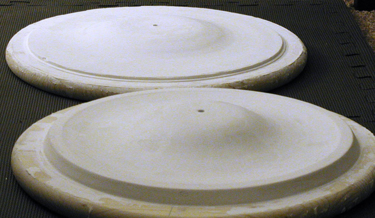 Because this process included a lot of waiting while each series of plaster applications dried/cured, I started working on some of the smaller masters. In the case of the rear nacelle caps, I created a contour from my plans on my computer and printed them out. I used this to cut out some ribbed styrene and then built up the part. 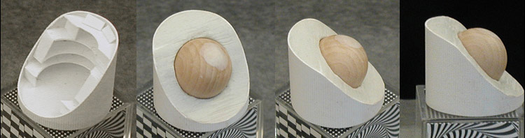 Sadly, I hadn't realized at the time that I had used the wrong side of the curve, and when comparing the test assemblies later I would catch the mistake and have to build a new master and new parts from it. 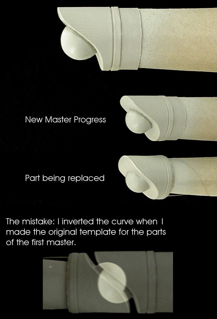 I continued working on the nacelle masters, including finishing the inner channel detailing. And preparing to mount them on a board for making the molds. 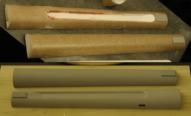 The ridges towards the front of the nacelles prove time consuming. I started with styrene disks of the front nacelle diameter, and then glued smaller (but thicker) disks to them. I then filled the step between with putty and sanded to get a nice, sharp surface on each. When the four disks came together they form what I needed. 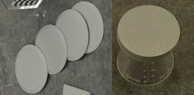 I also started in on the master for the B/C deck structure. Like on my smaller models, I formed the general shape in layers of foamcore board and sculpted the final shape around it. Once I was happy with the relative shape of the upper and lower primary hull masters, I coated them with Elmer's glue as a glaze. Once that set, I started adding in detailing (the engraved rings on the lower hull) and fixing flaws using glazing putty. After a few round of sanding, puttying and priming the surfaces, I felt like I was getting to where I need to be. This is my progress at that point with the B/C deck structure master sitting on top. 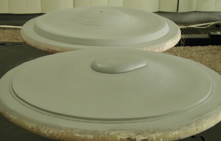 The next small part to work on with the intercool loop. While I would make just one, the mold would be used to make 6 parts for the final model. I built it up as layers of sheet styrene, then sands and puttied until I got the shape I wanted. This is a test of it with some of the other master. 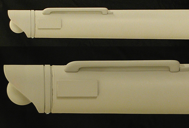 Building the MoldsWith most of the masters done, it was time to start making molds. I built my molds with layers of silicon rubber, then built up a plaster jacket on them to supply structural support. I included burlap in the plaster jacket for additional strength. This is what I ended up with for the lower primary hull. 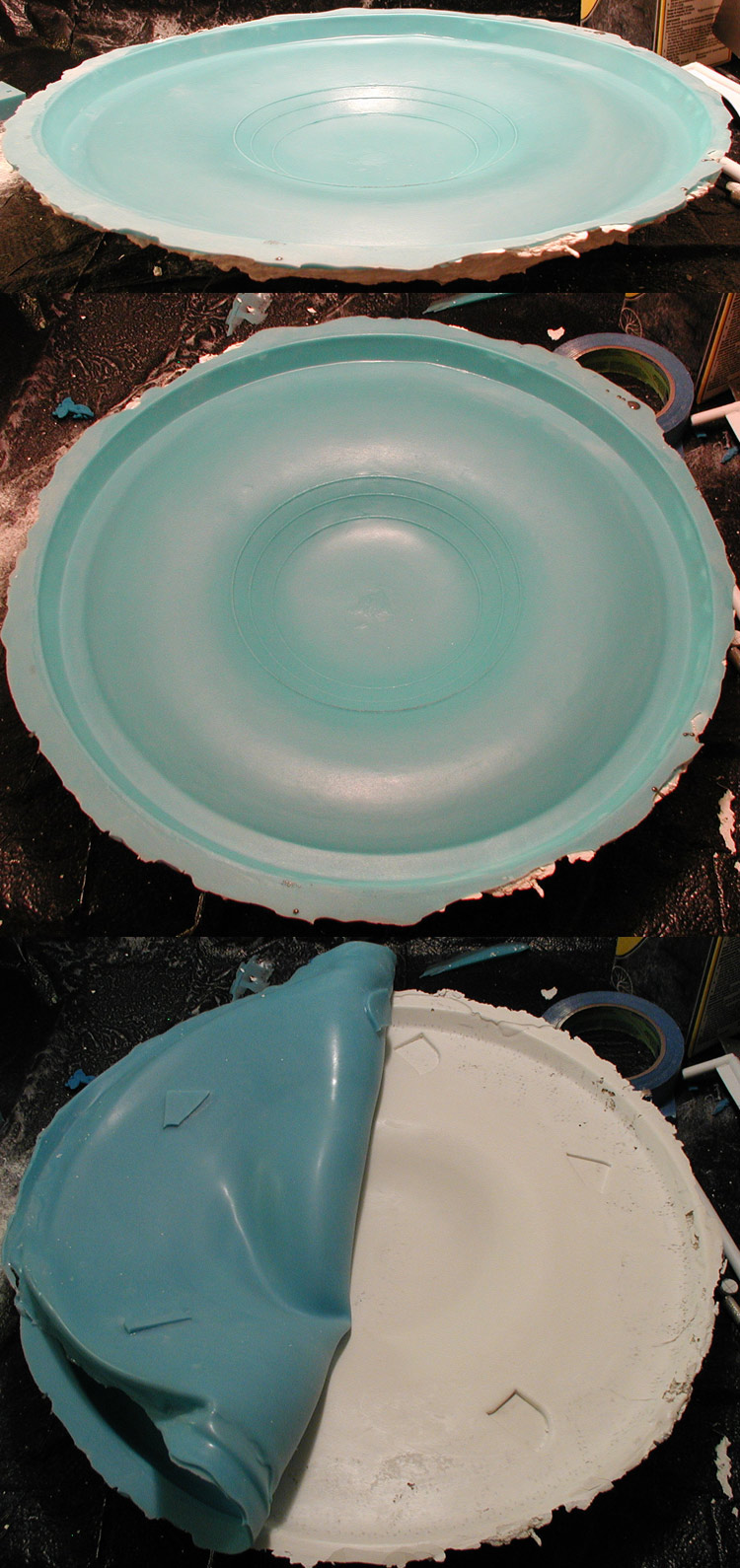 While the nacelles got one board to themselves, I was able to get most of the rest of the master onto a second board for making the molds. 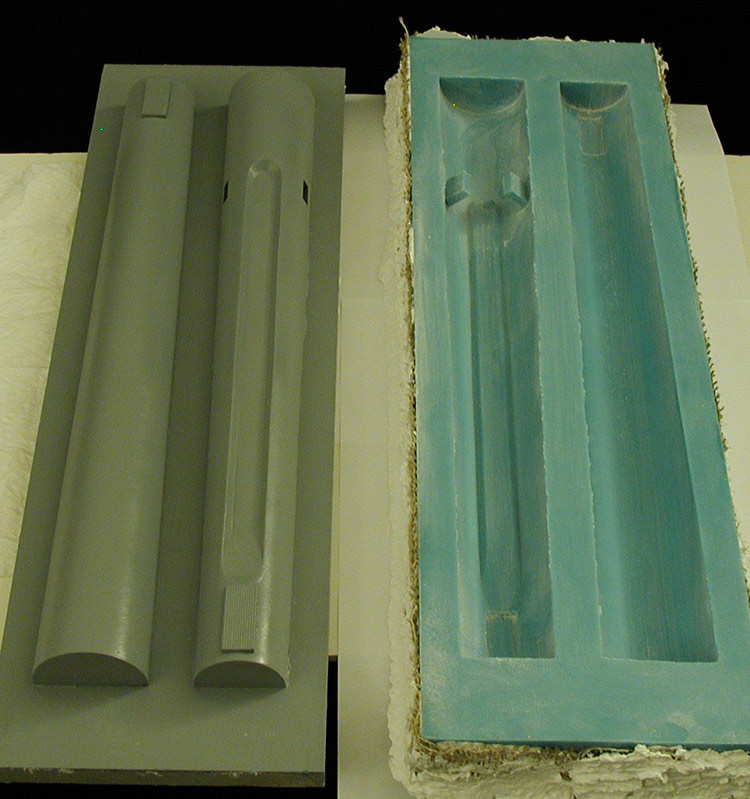 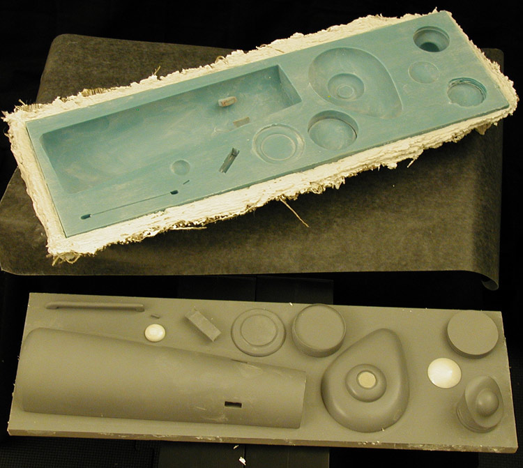 CastingAs each of the molds were finished, I started casting the parts. For the smaller parts I used Alumilite White resin, but for larger parts that would need to be more structurally rigid I used TC-1630 UltraCast polyurethane re-enforced with fiberglass cloth. I cast the upper and lower primary hull parts first. I added some aluminum rods to the lower hull to help it structurally (though it really wasn't needed) and a section of burlap cloth and a metal plate that would be used as the anchor point for the dorsal pylon. 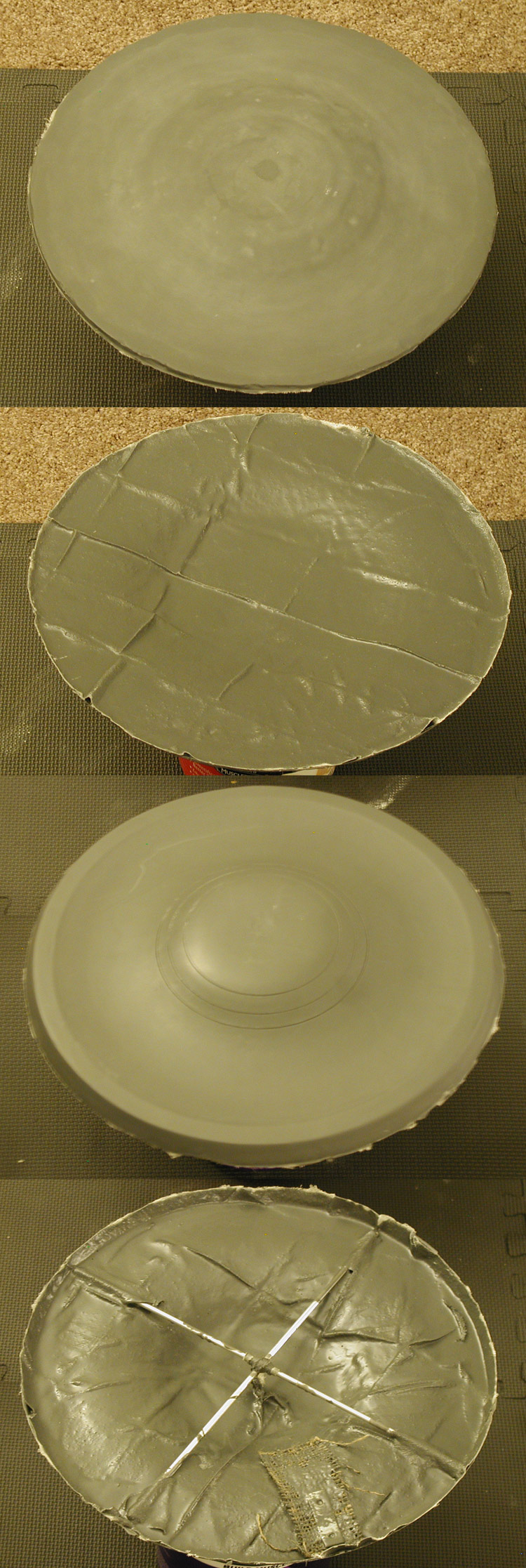 And once trimmed up a bit, the parts placed together formed a nice primary hull. 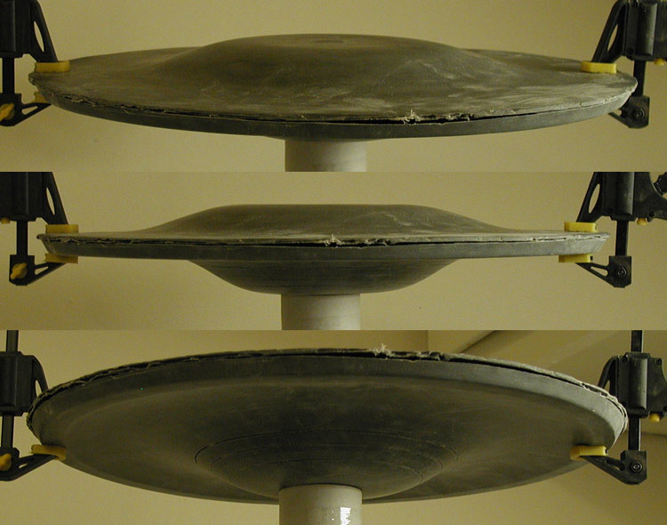 The parts were united using a combination of CA and Apoxie Sculpt. The bridge/B/C deck structure (made from Alumilite White) was glued in place with CA and I started in on cleaning up the rough edges using Bondo Glazing & Spot Putty (and coats of Rust-oleum Automotive Primer). 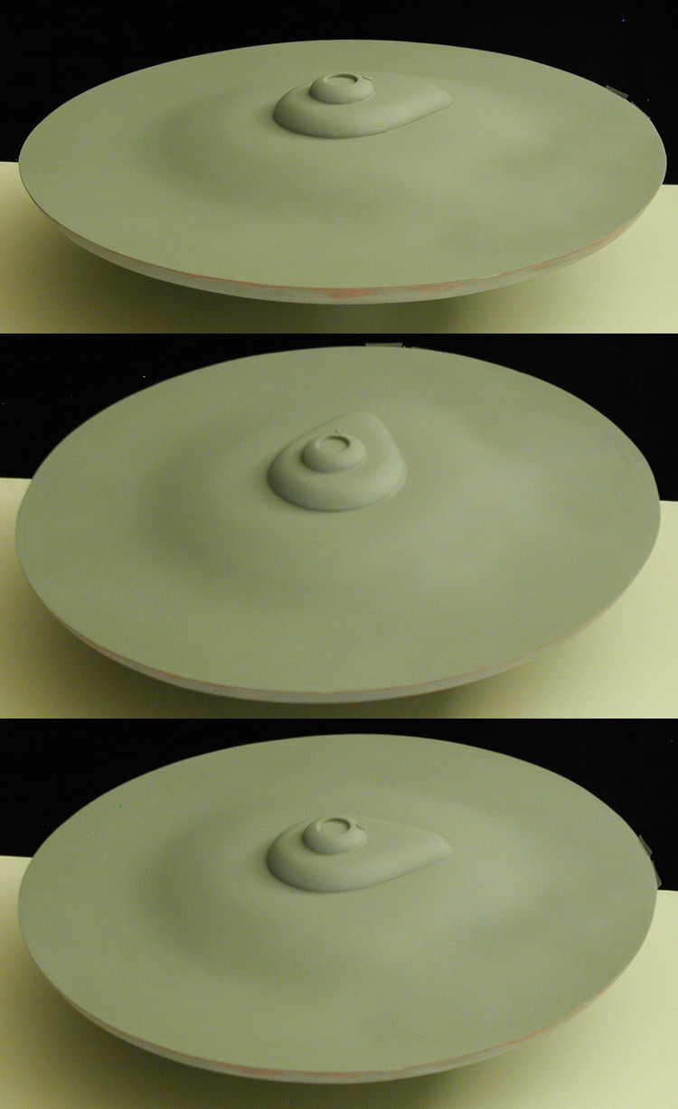 The next major hurdle was the dorsal pylon. It was constructed from two wood dowels, the front one was 19/32 of an inch in diameter and the rear was 1/2. Between them was a sheet of foamcore board to keep their relative alignment and pieces of sheet styrene for the sides. 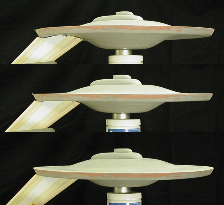 I had already drilled a hole in the primary hull for the screw that would lock it to the dorsal (matching up with the metal plate inside). When the screw was inserted, a large section of it stood out from the primary hull. That section would be embedded in the dorsal. 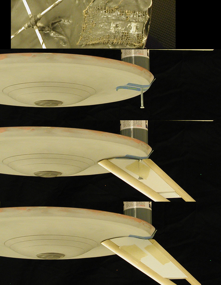 With the dorsal started, I cast the two halves of the secondary hull. As pointed out earlier, the mold was universal (design to make both sides). 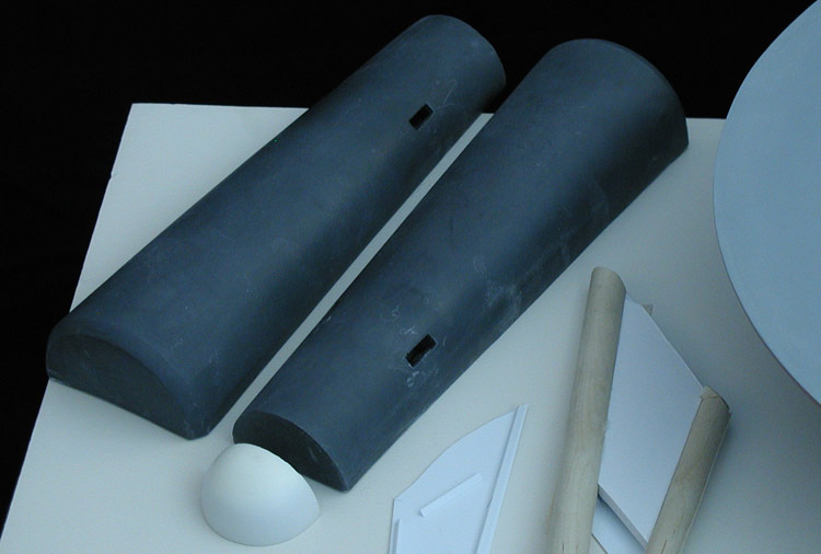 This left a lot of the details missing, and one of the nacelle support pylon holes would need filling on each. This was a test fitting of the two sides together after cleaning up the edges. 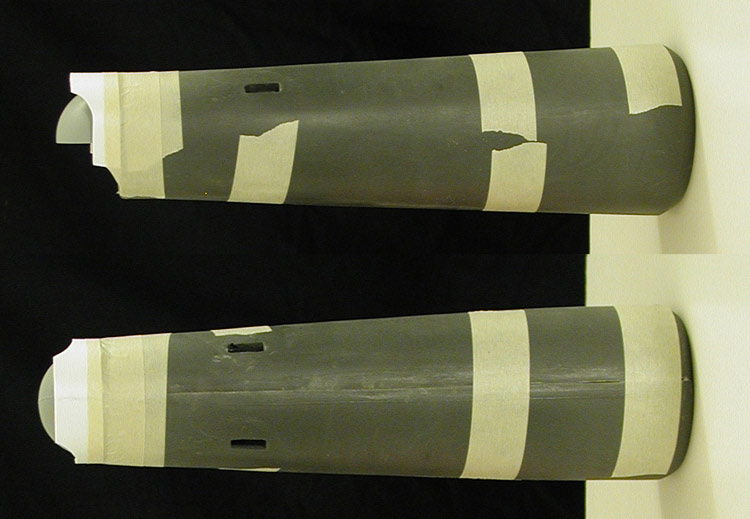 And this was after I started cutting in the rear undercut and side insets. 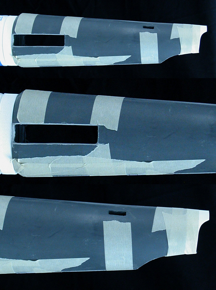 Had I realized how strong TC-1630 UltraCast was, I would have included the inset features in the original master. To make sure that everything was coming together as I had originally planned, I made some stand-in nacelle support pylons out of foamcore board and did a quick test assembly with the dorsal pylon.  Even with everything loosely taped in place, the alignment -specially the nacelle support pylon holes which were part of the cast secondary hull halves- seemed to be working nicely. This is with the primary hull just set in place.  This left casting the nacelle bodies. I did test making a nacelle with Alumilite White re-enforced with fiberglass cloth (wanting to make them less heavy), but wasn't really happy with the result. This was the first set of nacelle parts made with TC-1630 UltraCast with fiberglass.  This is another test assembly (including the Alumilite White nacelle) checking the alignment.  The stand-in nacelle support pylons weren't going to support the weight of the nacelles, so I started in on constructing the actual parts. The front and rear edges were styrene tubes. Between them were smaller aluminum and styrene tubes sandwiched between styrene sheets. The openings on the nacelles and secondary hull were built with this design in mind, so the parts of the supports that extended out fit snugly into the holes. Here is a progress shot with them next to the dorsal pylon. 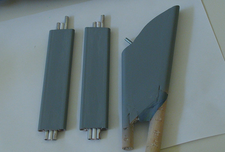 The reason for including a styrene tube between the aluminum ones was to make sure that everything was well anchored together (in case the glue didn't bond securely to the aluminum tubes). The deflector assembly was the next challenge. The outer shell was made from sheet styrene while the inner rings were made from cardboard rocket tubes. The dish was hand sculpted using Apoxie Sculpt. 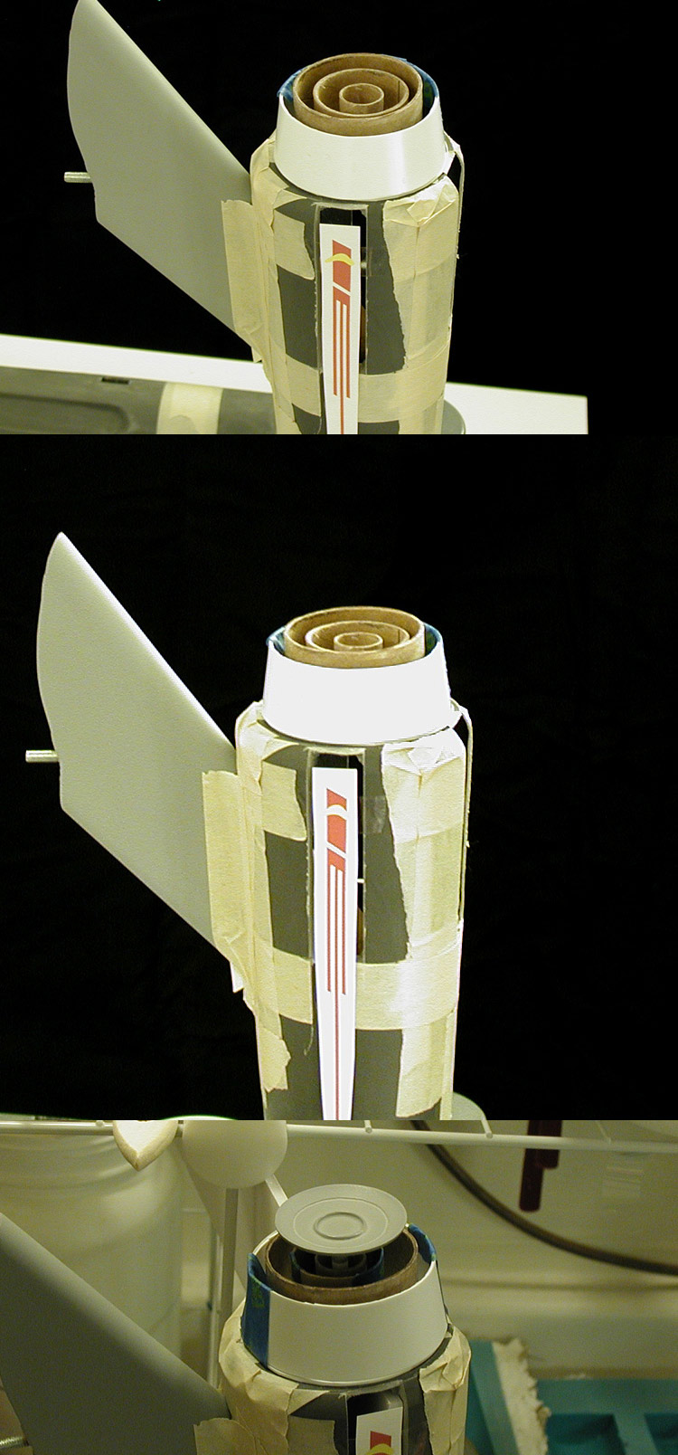 Of course all of this would be a massive waste of time if the model couldn't support itself. So after giving the nacelle support pylons a few weeks to completely cure/harden, I let them attempt to support the weight of the nacelle bodies. 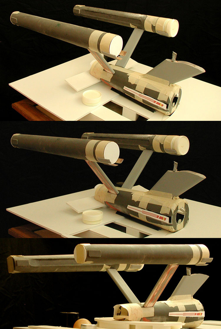 When I was sure that they were supporting the weight without twisting, I did a second test with most of the nacelle parts in place (making them heavier). 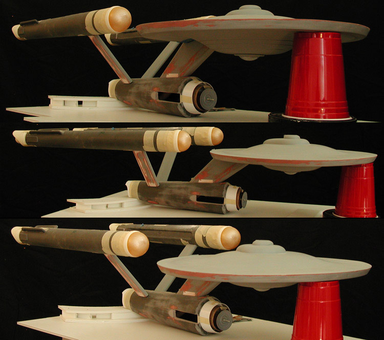 Alignment BoxUp to this point the dorsal pylon was only taped in place, and the attachment points for the nacelle support pylons had some play (by design so I could make minor adjustments later). Before I could lock key aspects in place I would need a way of making sure that everything was aligned correctly. I needed to build an alignment box for the model. 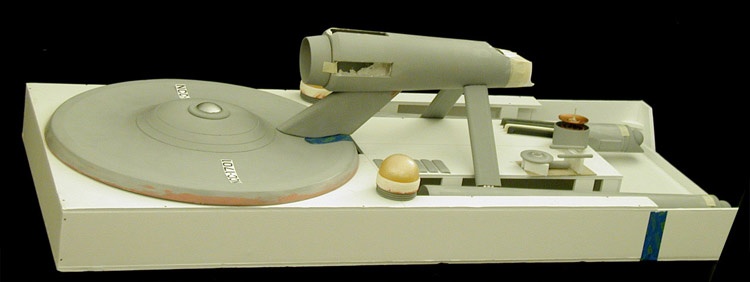 I had built one for my Phase II Enterprise study model, which while smaller had the added issue of angled nacelle support pylons. 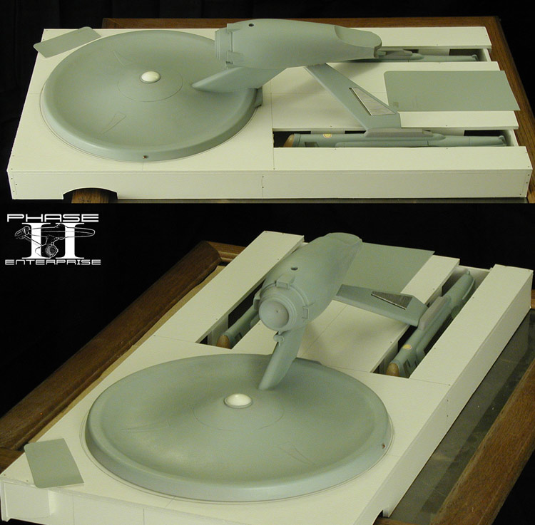 With everything aligned, I glued the dorsal pylon in place and started filling the secondary hull with AMACO Sculptamold (cellulose-based paper maché). This stuff sets up super solid, so I knew that the dorsal would be completely anchored inside the secondary hull. Once the first couple applications had been allowed to cure, I knew that the dorsal could support the weight of the primary hull on it's own. I cut the opening in the top rear of the hull so I could lock the dorsal screw in place with a nut. Then I let the model stand on its own (here with test prints of the decal graphics I was designing). 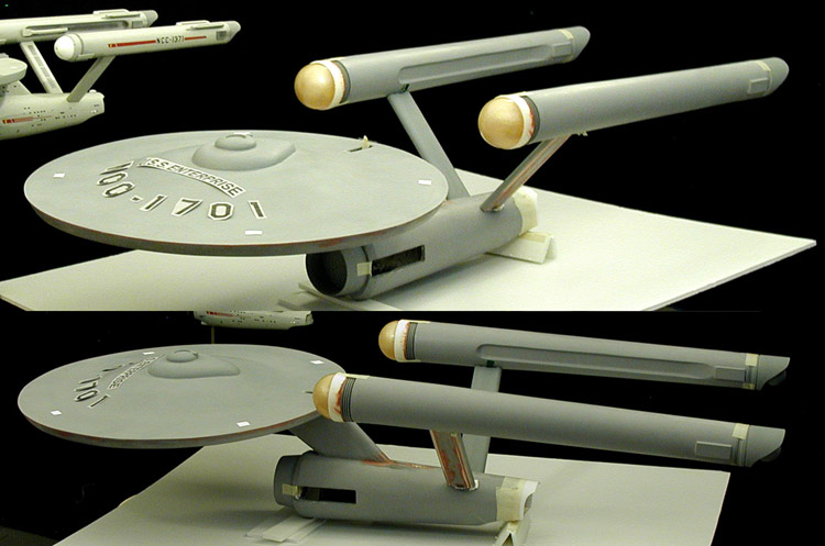 Historical RecreationI realized pretty early on that this was going to be a one of a kind model. The original is long gone and there is no point in a commercial kit of this model when everyone already has the 1/350 Round 2 model. This was intended as a historical recreation, a resurrection of a lost artifact. As such, I knew that I would run into an issue that I couldn't scratch build. The last time that Richard Datin worked on the original model was in December 1966 when he was ask to make a display stand for the model. The stand consisted of a 12 inch by 12 inch wood plaque base, a chrome goose neck arm and a microphone quick release assembly. 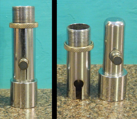 So for this model I bought the needed vintage (mid-1960s) parts. And I knew that I'd be embedding part of the quick release into the secondary hull as I slowly filled it with the Sculptamold. In this series of test assembly images you can see that the back end of the secondary hull has been filled (it is the white area of the undercut). 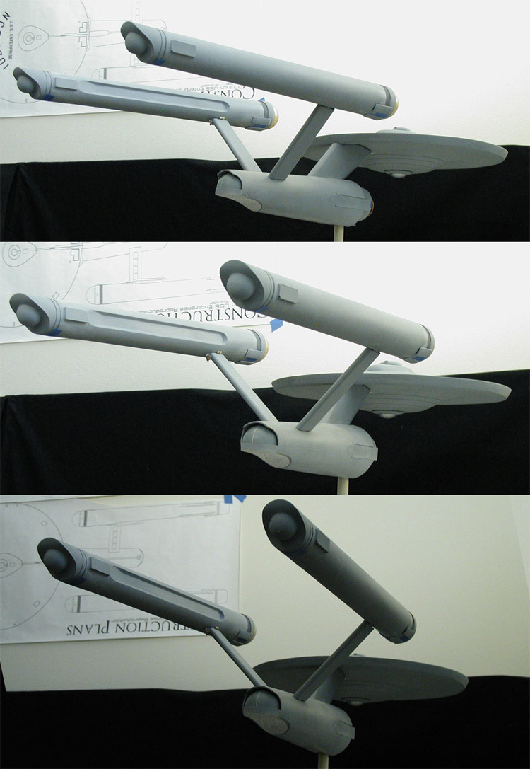 Once I worked my way towards the front, I embedded the top part of the quick release in the hull. And after letting it fully cure, I took a few more test assembly shots (again with the printed test graphics). 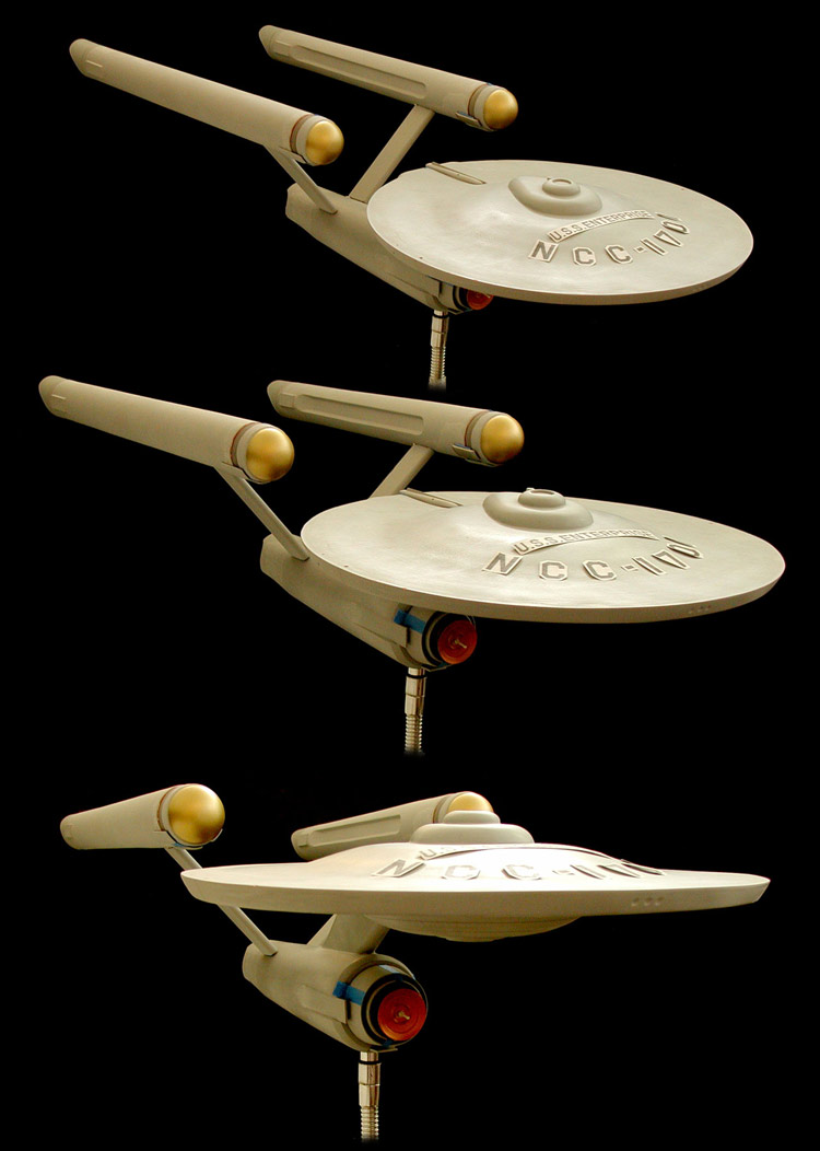 Then I took ill and wasn't able to work on models for quite some time. Most of my model stuff went into storage, but I was eventually able to bring home all of the key elements of this model. 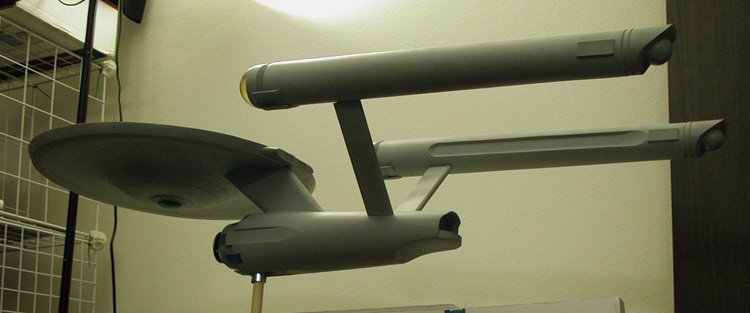 One way to look at this is as a test. From the time I brought those parts home (spring/summer of 2017) to when I started back on it in January 2019, the model sat assembled (but not glued) supporting its own weight. If it was going to have issues, they most likely would have shown up during that period. Instead it waited patiently for me to get back to it. I did a few things in that time, but for the most part it just sat there. 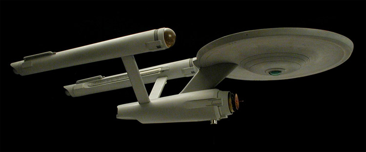 Again, the model wasn't actually glued together yet. This is what it looked like when not assembled. 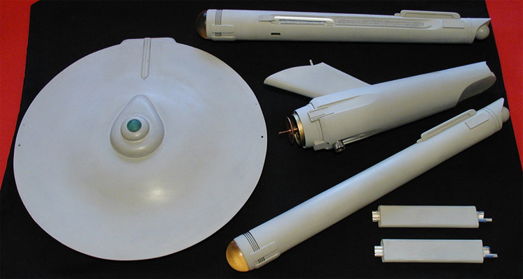 Hull Graphics and DecalsThe development of the decals for this model actually predate the start of the build. This shouldn't be surprising as this was part of the research for the plans. With the first two study models I used pre-existing third-party decals as I hadn't done enough research to warrant custom made decals at that point (2009/2010). Starting in 2012 I began reverse engineering graphics based on the original decal sheets used for both the 11 foot and 33 inch studio models, where I drafted every character rather than attempting to use a pre-existing font. Oddly enough, this model wasn't the first to use those graphics. I actually used them for the custom decals made for my Phase II Enterprise study model. Below is the most recent example of my findings, including the graphics meant for the 11 foot model. The yellow areas represent a clear lacquer applied over the graphics to (I believe) protect the ink when transferring them to the models. 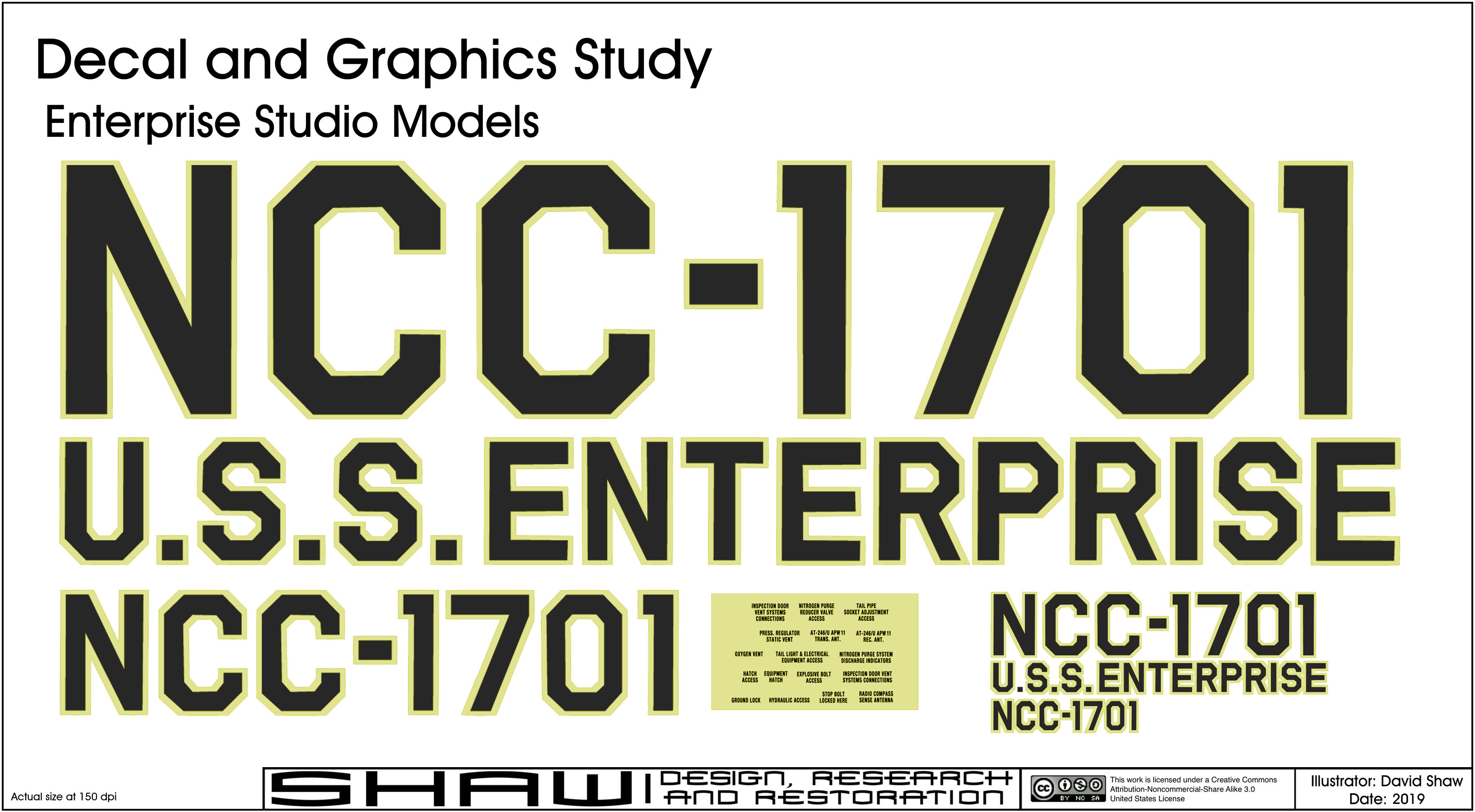 Click to enlarge The lacquer does appear yellow on the decal sheets, partly because of aging, but was intended to be clear on the models. In the case of this model, there is evidence that the yellowing was visible during the 33 inch model's production career, so I opted for yellowing on upward facing graphics, a slight gray outline on downward facing, and a transition from yellowing to gray on side graphics (the registry on the nacelles). These are transparent colors, so are not always visible in photos and can be missed in certain lighting in person (replicating the original model). While this part of the decals were mostly done before the start of the build, other aspects were finalized only in the last few months before I actually applied the decals. The pennants on the nacelles and secondary hull were finished earlier on (and yes, they are different from those of the 11 foot model), but the other markings and the windows proved to be something of a chore to both create and arrange on the decal sheets. In the end I realized I would need more than one sheet, so I held off finishing the layout of the second sheet until after I had successfully applied the decal graphics from the first. This was so I could add on any replacements if I messed up in the application process. On previous (smaller) models I often included multiple copies of the graphic elements on a single sheet to allow for mistakes. The Finished modelHere is a few shots of the essentially finished model... 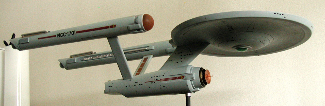 Click to enlarge 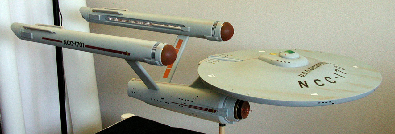 Click to enlarge 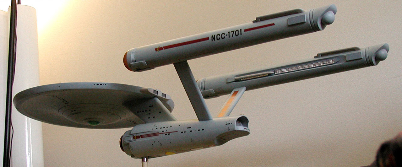 Click to enlarge 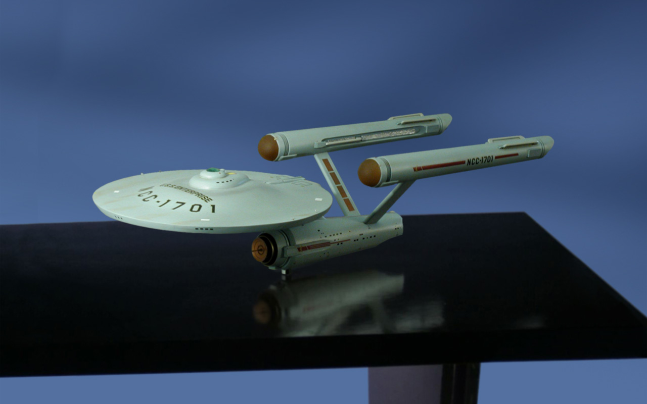 Click to enlarge 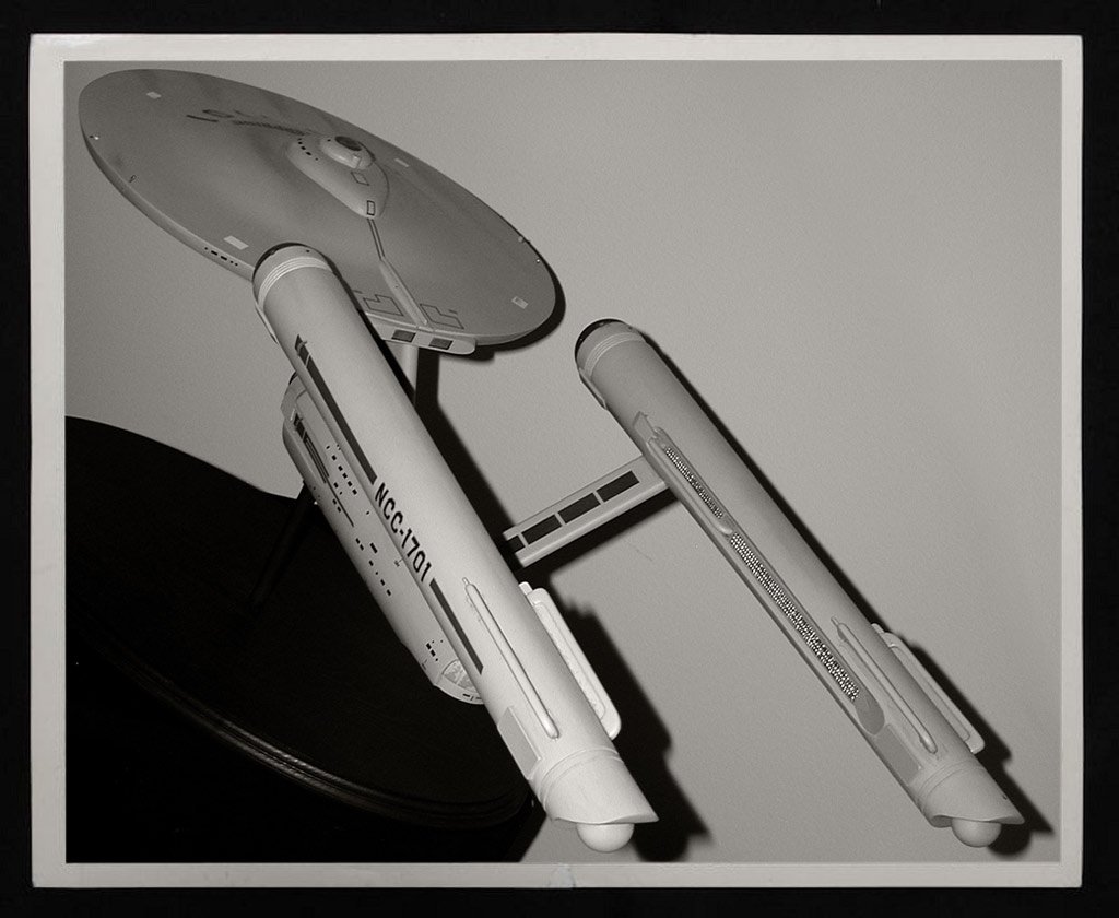 Click to enlarge And some more shots can be found here...   |
